Cubit
15.3 User
Documentation![]()
Cubit
15.3 User
Documentation![]()
Sculpt options for specifying the methods for generating nodesets, sidesets and blocks on the mesh. Several automatic methods for generating nodesets and sidesets are provided in Sculpt using the gen_sidesets option. Where multiple blocks are required, Block IDs are normally defined using the material ID in the diatom file. Each STL file can be associated with a different block ID. If the mesh_void option is used, the ID for the block of elements in the void region can be set using the void_mat option.
For other input formats such as volume fraction microstructure data or Cartesian Exodus files, the Block IDs are defined by the individual formats.
Boundary Conditions 		--boundary_condition 	-bc
  --void_mat,		-VM <args>	Void material ID (when mesh_void=true)
  --gen_sidesets,	-SS <args>	Generate sidesets

Sculpt Command Summary
Command: void_mat     Void material ID (when mesh_void=true)

Long Name:     --void_mat
Short Name:     -VM
Argument Type:   integer > 0
Command Description:
When the mesh_void option is used, this value is the material (block) ID
assigned to all elements in the void region. If void_mat option is not used,
the material ID of elements in the void region will be the maximum material
ID in the model + 1. Note that the void_mat may be the same as an existing
material in another part of the model.
Generate Sidesets
Command: gen_sidesets     Generate sidesets

Long Name:     --gen_sidesets
Short Name:     -SS
Argument Type:   integer (0, 1, 2, 3, 4, 5)
Input arguments: off (0)
                 fixed (1)
                 variable (2)
                 geometric_surfaces (3)
                 geometric_sidesets (4)
                 rve (5)
Command Description:
Generate exodus sidesets using one of the following options:
off (0): No sidesets will be generated
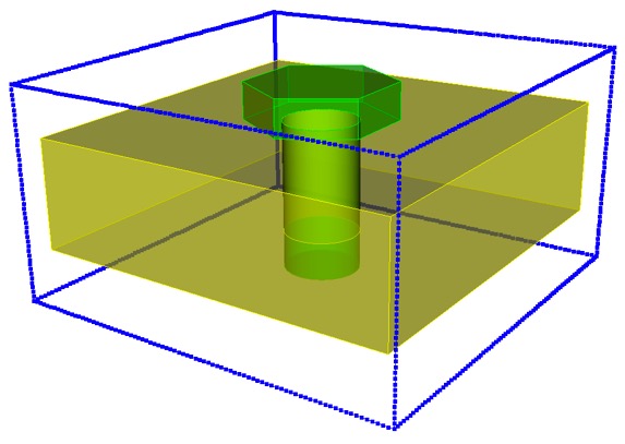
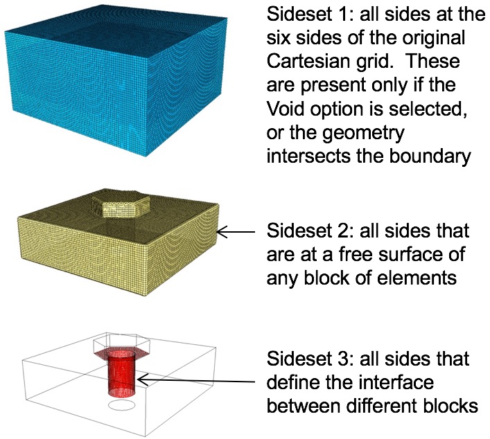
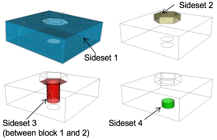
fixed (1): Exactly 3 sidesets will be generated according to the following:
Sideset 1: All sides at the domain boundary. Sides will only be present in this sideset if the model intersects the enclosing bounding box or the void option is used.
Sideset 2: All sides at the model boundary. Any side on the model that is not interior will be included. This should represent a full enclosure of the model if it does not intersect the domain boundary.
Sideset 3: All sides at material interfaces. Includes sides on the interior where adjacent blocks are different.
variable (2): A variable number of sidesets will be generated with the following characteristics:
Unlike Fixed sidesets, grouping of sides will be contiguous. A separate sideset will be generated for each set of contiguous sides.
geometric_surfaces (3): Sidesets will be generated according to imported surface ID information. STL files may include an optional surface designation for any or all triangles in the file. Surface information may be written automatically from Cubit based on geometric surface IDs or sideset IDs. See the cubit sculpt parallel sideset option for more details. If present, one sideset will be generted for each surface designation in the STL file. Following is an example surface designation in an STL file. It would appear following all triangles.
            surface 1
              0 1 2 3 4 5 6 7 8 9
              10 11 12 13 14 15 16 17 18 19
              20 21 22 23
            endsurface 1
The id following the surface designation will be used as the sideset ID. Up to 10 triangle IDs, per line may be assigned to the surface. Triangle IDs are assigned based on order they appear in the STL file. Any number of surfaces may be defined. For this option, the assumption is that all triangles included in the STL files will be included in at least one surface designation.
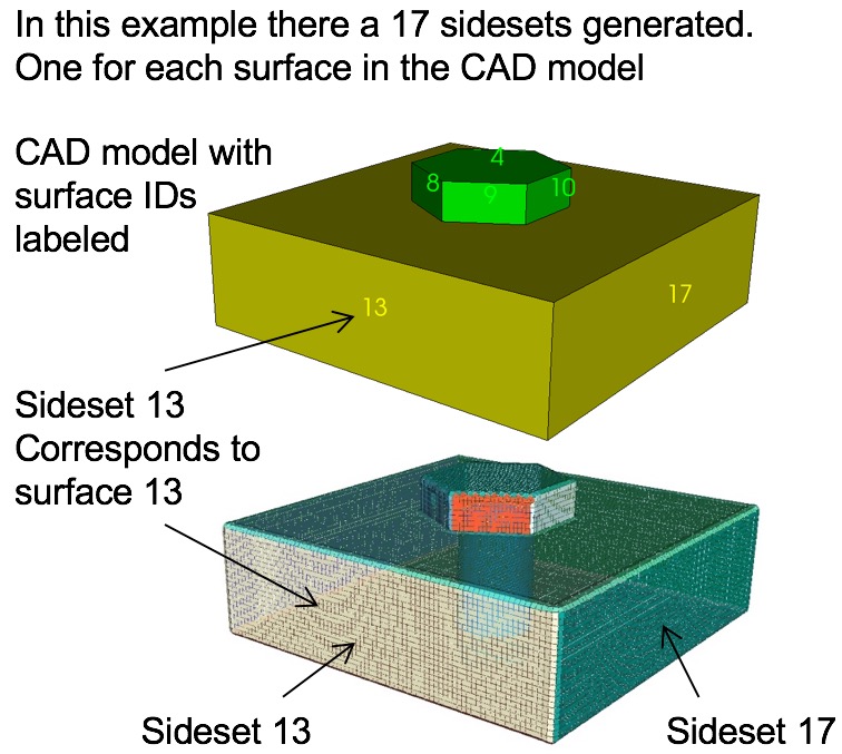
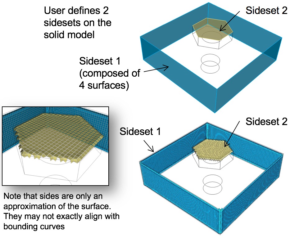
geometric_sidesets (4): Similar to geometric_surfaces, except that only a portion of the triangles may be designated as sideset surfaces. This option is useful when using Cubit to identify specific surfaces as sidesets.
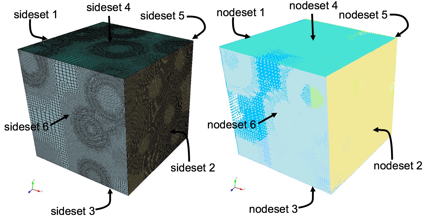
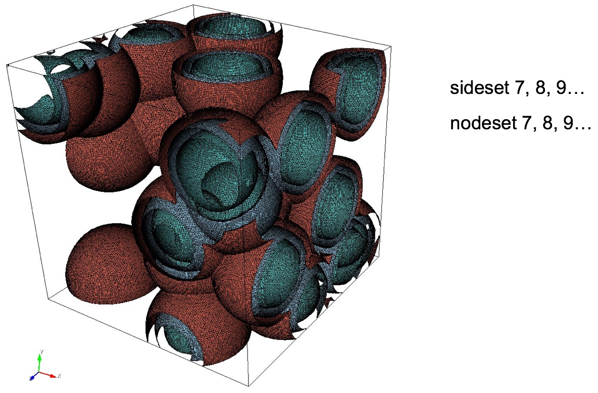
RVE (5): When using the full bounding box, such as representative volume elements (RVE) for microstructures, the nodesets and sidesets with IDs 1 to 6 are reserved for the six faces of the bounding box. They are assigned as follows:
            Nodeset/Sideset ID      Contains nodes/faces
                   1                on minimum X domain boundary
                   2                on maximum X domain boundary
                   3                on minimum Y domain boundary
                   4                on maximum Y domain boundary
                   5                on minimum Z domain boundary
                   6                on maximum Z domain boundary
In addition, a nodeset and sideset will be generated on interior surfaces for each unique pair of adjacent material IDs. One final nodeset will also be generated along interior curves at all internal triple junctions (curves where at least 3 surfaces share a common curve).