“Courtesy Sandia National Laboratories, SUMMiT™ Technologies, www.sandia.gov/mstc”
We require credit be placed prominently near or underneath the photo or movie.
Thank you for using our web site.
MEMS Videos
World’s Smallest Mite-Go-Round
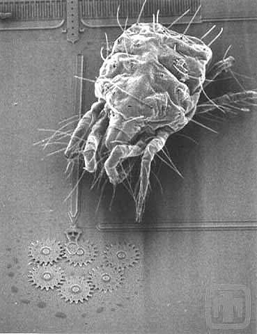
Two dust mites taking a spin atop an optical shutter running at low speed. The mites’ limbs are flailing due to the slickness of the silicon wafer.
Aphid on Micromirror
This aphid (considerably larger than the dust mites) crosses a micromirror, catching his feet on suspension springs as he travels. Note the mirror still operates after being bug-stomped.
Spider Mite Crossing Large Gear
This spider mite is on construction duty; as he crosses the large wheel, he leaves a gear guide for future assembly. Silly bug – doesn’t he know that these systems are batch fabricated and no assembly is required?!
Spider Mite Riding Large Wheel
This spider mite decides to ride the large wheel as it reverses directions.
Spider Mite Test
This micromirror continues to be operational even after being tested by the spider mite.
High Speed, Low Drag
This clip shows that Sandia MEMS motors can rotate large wheels and drive a substantial load (the spider mite), all at very high speeds. Future wheels may include spider mite handrails.
Comb Drive Close-up
This is a close-up view of a microengine comb drive in operation. The visual contrast changes with the electrostatic charge.
Comb Drive Wide Field
This video presents a wider view of the visual contrast changes.
Signal Lines
The lines delivering the drive signal to the comb drives of our running microengine are visible in this video. As above, the visual contrast changes with the applied voltage.
Bond Pad
In the lower left corner of these frames, is the wire which transmits the drive signal from the power source. The wire is attached to the bond pad of the microengine, from which the signal flows along traces to the microengine.
Gear Powered by Microengine
This is a gear being driven by one of our microengines. The SEM provides unprecedented magnification, although when viewing moving objects, real-time, the detail visible is a fraction of that of a still image.
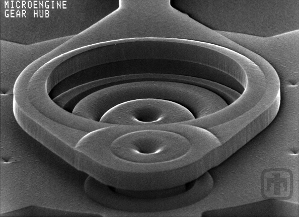
Gear Hub Close-up
This is a close-up look at the hub of a moving gear. The greatest advantage of running MEMS in an SEM is the ability to view wear on moving parts, real-time, at extreme magnifications.
Linkage Arm and Comb Drive
The linkage arm and comb drive, using our voltage visual contrast technique to show where the voltage is as it drives the engine.
Comb Drive Wide View
Here is a wider view of the microengine in operation, which more clearly shows how the voltage changes on the combs pull and release the engine so that it moves back and forth like a piston.
Six-gear Planar Train
There is a trick to keeping the gears in this six-gear train correctly meshed when they are only about two microns thick – they are held in plane by flat guide plates which are mounted to the tops of the shafts.
An Overview of the Six-gear Planar Train
Six-gear planar train operating at variable working speeds.
Six-gear planar train operating at a fast speed.
Close-up video of the six-gear planar train in operation
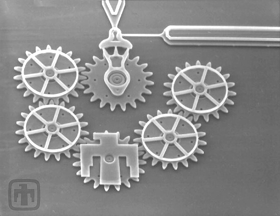
Five-gear Planar Train
In this clip is a chain of 5 gears of various sizes being driven by a microengine moving at the amazing speed of 60,000 RPM.
Transmission Driving “Large” Gears
Here a transmission drives two of our largest gears – each is more than a millimeter in diameter.
Transmission Driving “Large” Gears – Clip Two
The two large gears are being driven by a microengine operating at 6000 RPM. The transmission has been driven at speeds as high as 60,000 RPM.
Spring Device
Here a spring device is wound and unwound. Perhaps one day a micro-clock can be made with this type of mechanism.
Spring Device – Clip Two
In this video, the spring is wound and unwound by a microengine operating at 6000 RPM.
Linked Gears
Here, a transmission drives two linked gears while the microengine runs at 60,000 RPM.
Torque Demonstration
This is a microengine driving a gear approximately 40 times its own diameter, demonstrating the large torque it can produce.
Microengine and Gears
This microengine’s drive gear is turning a 250-tooth gear more than 10X as large as itself. The speed of the drive gear is 600 RPM, and it has been operated as fast as 60,000 RPM.
Microengine, Transmission, and Spring Device
This video pans from the microengine driving the device, through a transmission that multiplies the torque, to a spring that winds-up and drives additional gears.
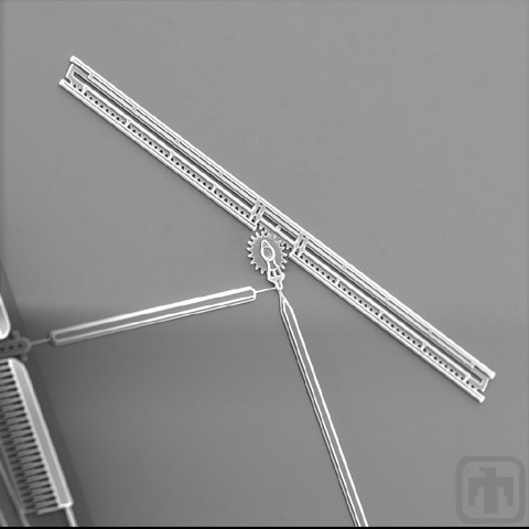
Linear Rack
A comb drive actuator rotates a drive gear, which in turn drives a linear rack back and forth to its full extents.
Linear Rack (High Speed Operation)
The same linear rack as above, operating at full speed (less than 0.04 seconds travel time).
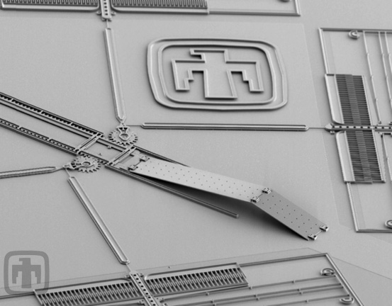
Pop-up Silicon Mirror
Force provided by a comb drive actuator moves a linear rack, which drives a hinged sheet of silicon back and forth. A HeNe optical-band (red) laser is focused at an angle such that as the mirror is elevated, the coherent light is reflected into the microscope’s camera.
Pop-up Silicon Mirror (High Speed Operation)
The same pop-up mirror as above, this time operating at full speed. The high switch rate of the mirror (35 milliseconds) validates its potential for use in optical switching.
Pop-up Silicon Mirror (High Speed Operation)
Although just a blur, this is actually the mirror being raised and lowered by a microengine operating at over 100,000 RPM.
Deflection of Laser Light
Here a mirror is slowly raised and lowered to show the deflection of laser light.
Pop-up Silicon Mirror
In this video, the mirror is shown being elevated in less than two-thousandths of a second.
Demonstration of Switching Speed
The switching speed (time required to deflect optical energy) can range from 2.67 milliseconds for fullly raising and lowering the mirror to 1.18 milliseconds for smaller angle deflections.
Torsional Ratcheting Actuator
The torsional ratcheting actuator (TRA) is running at a slow, constant speed. By visually following the dot on the outer ring which starts out at 3 o’clock position, the ring’s rotation can be seen.
Torsional Ratcheting Actuator Close-up
In this close-up, the camera pans across the lower half of the TRA device. Again, it is running slowly so its motion is clearly visible.
Torsional Ratcheting Actuator
As the camera finishes panning to the bottom right corner of the TRA, you can see our Sandia National Laboratories Thunderbird Logo. To put the size of the TRA in perspective, it is approximately one-third the size of our comb drive microengines.
Torsional Ratcheting Actuator
In this video and the next, the TRA is put through its paces; the TRA’s speed is doubled at regular intervals – from a 1 Hz drive signal up to 640 Hz – then it is slowed down again.
Torsional Ratcheting Actuator
Please note that the dot on the outer ring is moving almost too fast to see! We have operated the TRA with drive signals in the low kHz range, and will be able to increase that still further with future refinements.
Torsional Ratcheting Actuator Pawl Close-up
In this close-up of the ratcheting pawl (with black dot) operating at low speed, it is possible to see that with each cycle it pulls one tooth on the outer ring.
Rotary Motor
The rotary motor is operating at various speeds in this video.
Rotary Motor
In this video, the camera pans to the center of the rotary motor and then out to its edge.
A Newer Version of our Rotary Motor
The rotary motor operating at high speed.
A Newer Version of our Rotary Motor
The rotary motor operating at medium speed.
A Newer Version of our Rotary Motor
The rotary motor operating at slow speed.
Wedge Indexing Motor (Slow)
Wedge Indexing Motor (Medium)
High Speed Optical Shutter
The optical shutter directs a beam of light by passing it through apertures in the shutter. Here we demonstrate (real-time footage!) a switching time of 35 milliseconds.
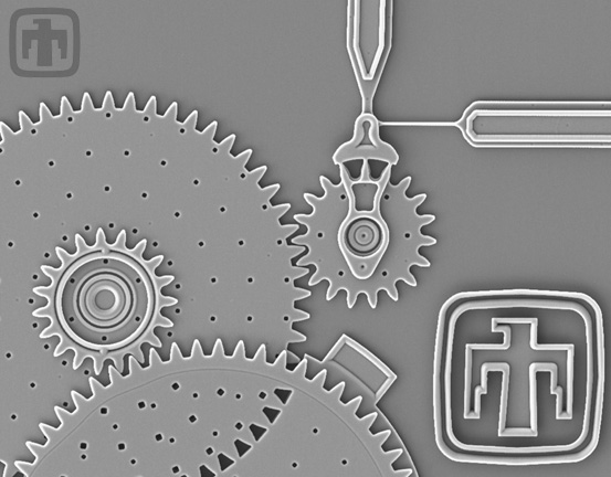
2-Bit Binary Encoder
The binary encoder wheel stops in any of four positions, each of which is associated with a particular shutter aperture. A single beam of light would be capable of up to four signals based on the wheel’s orientation.
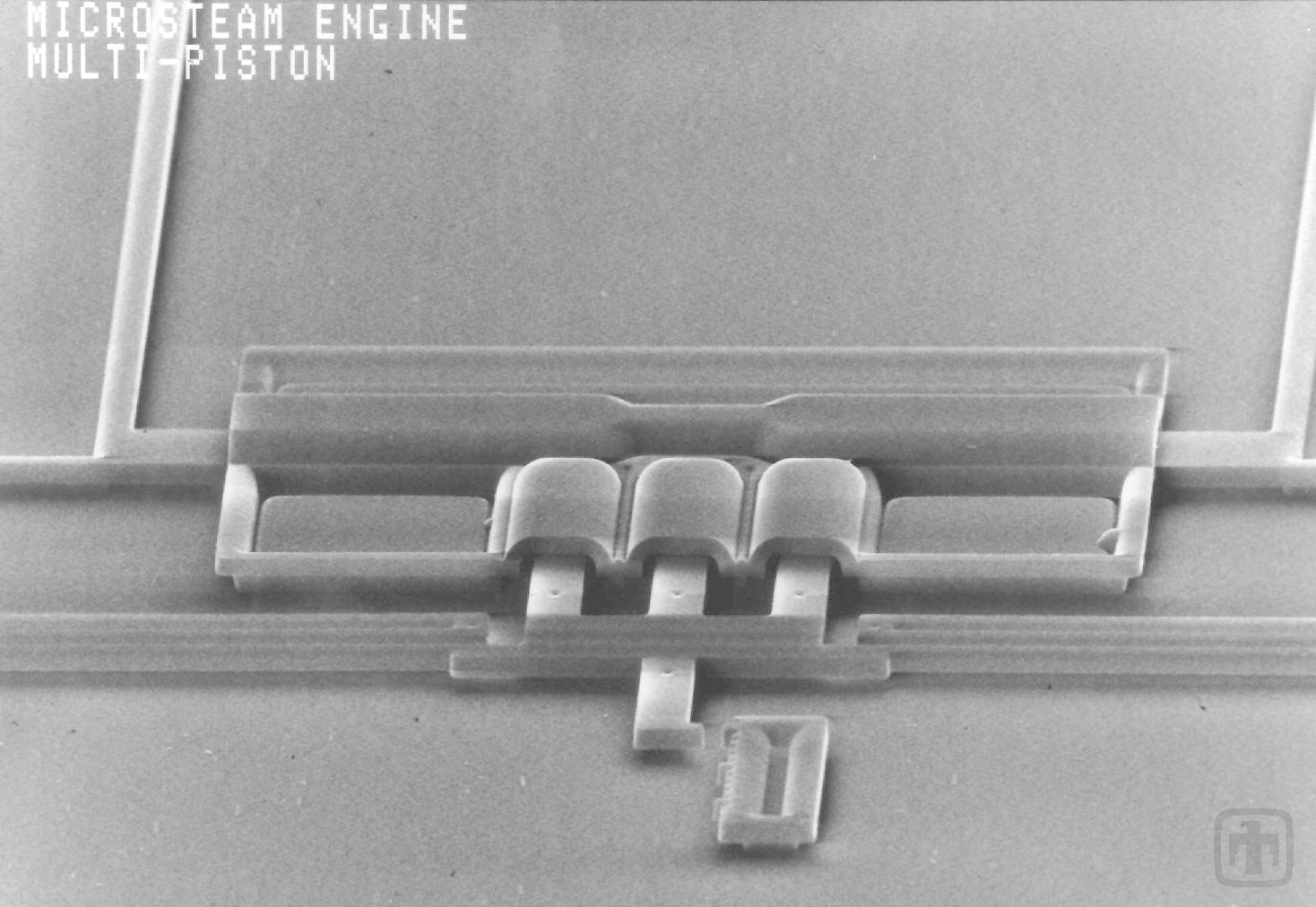
World’s Smallest Microsteam Engine
Water inside of the compression cylinder is heated by a flow of electric current and vaporizes, pushing the piston out. Capillary forces then retract the piston when the current is not flowing.
Opal
The video shows micromirrors that are erected on a rotating stage. A torsional ratchting actuator (TRA) and a gear transmission are used to turn the stage. The angled mirrors reflect a green LED that is positioned to reflect light into a video camera.
Short Stage
In this video clip a 16 mg solder ball that hangs over the edge of the stage had been placed on top. The actuators are still able to rotate the stage with the large (for MEMS) additional load and friction.
Plate Gyro
This video shows a capacitively coupled MEMS rotating stage with an on-board accelerometer. A thermally actuated ratchet rotates the stage in precise increments utilizing a 7 V square wave signal.
Plate Gyro with Si
A small silicon part has been placed on top of the rotating stage in this expanded view video. The two thermal actuators can be seen ratcheting the stage through a few degrees of rotation.
Plate Gyro with Solder Ball
In this video a 2 mg solder ball has been placed on the stage. The actuators have no problem rotating the stage with the added weight and resulting friction.
MEMS Images
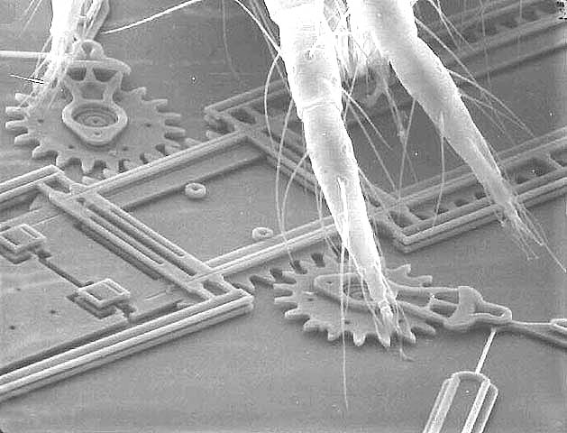
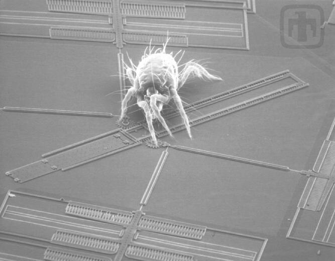
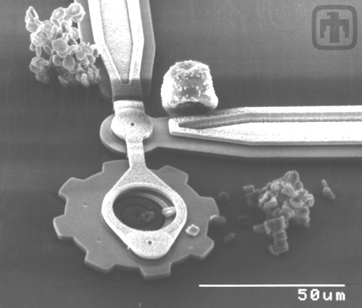
Mirror Mechanism with a Spider Mite
Spider mite with legs on a mirror drive assembly.
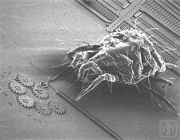
Drive Mechanism Dwarfed by Mite!
The tiny gears are dwarfed by a spider mite.
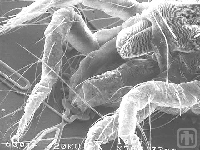
Another Example of a Bug and a Mechanism
Another Example of a Bug and a Mechanism
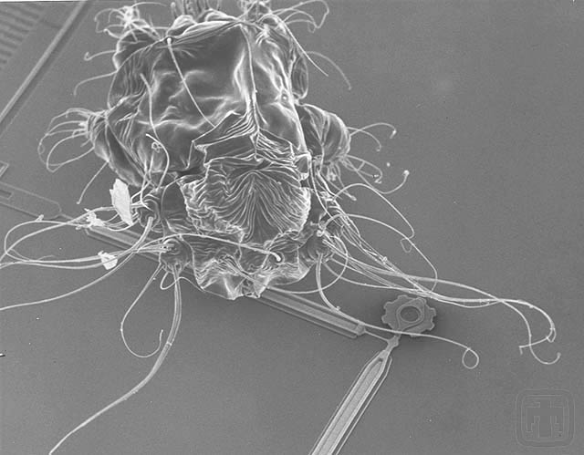
A Second View of the Mite Approaching the Gear Chain
Please note the relative size of the gears and the mite
A Gear Chain with a Mite Approaching
A Gear Chain with a Mite Approaching
Spider Mite and Gears
Spider Mite and Gears
Spider Mite on Mirror Assembly
Spider Mite on Mirror Assembly
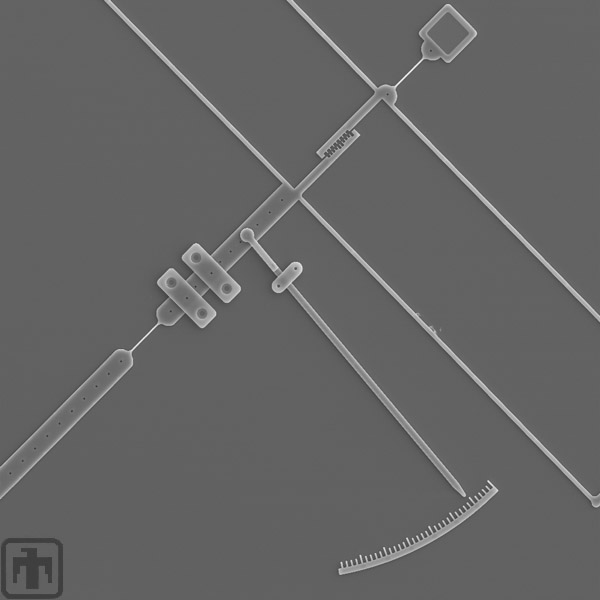
Micromachined Dynamometer
This micromachined dynamometer is used to determine the coefficient of friction by measuring the normal and tangential forces.
Pin Joint Close-up
This is a close-up look at the pin joint on the smooth "gear."
Flex Link Close-up
The standard microengine flex link is shown here, and is used to rotate the smooth "gear."
Dynamometer Beam
The beam shown exerts a normal force on the smooth "gear" of the microengine.
Dynamometer Verniers
Verniers for measuring deflection used to calculate the tangential force.
Vernier Close-up
Close-up of parallel vernier structure
Dynamometer Verniers
Verniers for measuring deflection used to calculate the normal force.
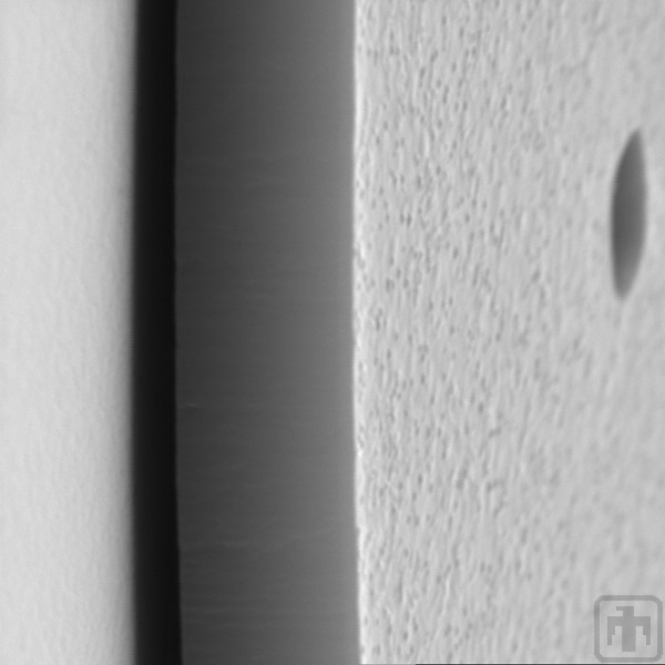
Contrast of Textures
In this image the texture differences between vertical and horizontal surfaces are visible.
Vernier Close-up
Close-up view of one vernier; the teeth are 2 microns wide and the spaces between them measure 4 microns.
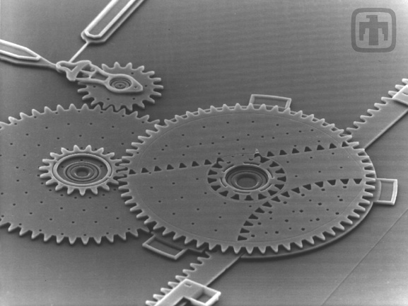
Multiple Gear Speed Reduction Unit
Top view of gear reduction unit.
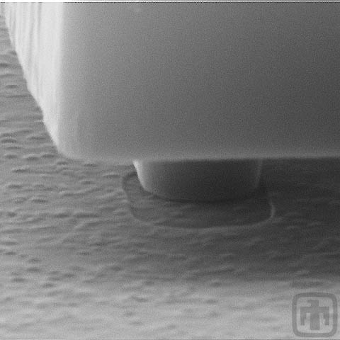
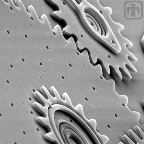
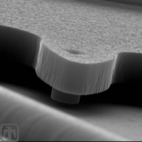
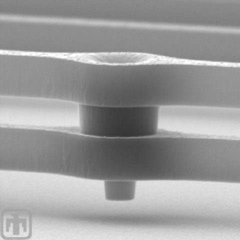
Do MEMS Have Dimples?
Yes. We call them dimples, but actually they are tiny bumps. This one minimizes microscopic tilt and wobble of a rotating gear.
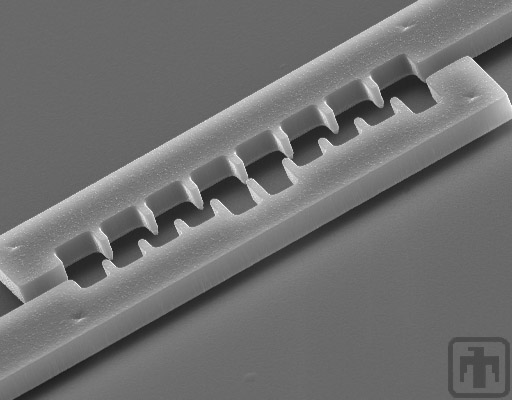
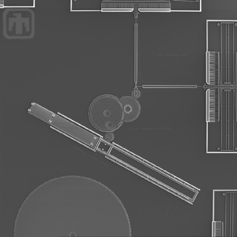
Linear Rack Gear Reduction Drive
This gear chain converts rotational motion (top left) to linear motion, thereby driving a linear rack (lower right).
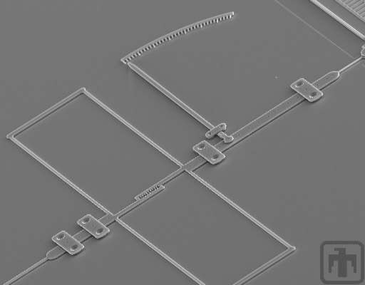
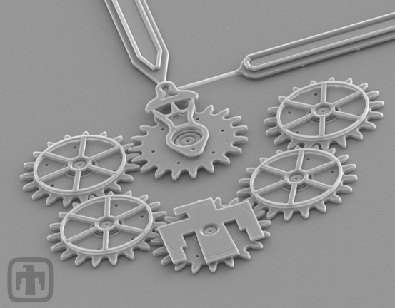
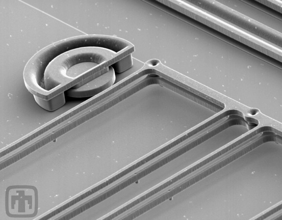
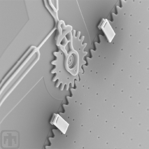
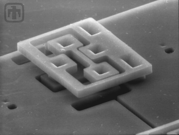
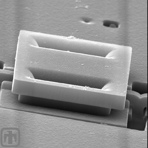
Alignment Clip
Meshing MEMS gears is similar to meshing two sheets of paper; they are very thin and must be precisely positioned. We use alignment clips to ensure these co-planar gears remain in plane and meshed.
Alignment Clip
This alignment clip is used in conjunction with a transmission (please note that there are 2 layers of gears). This complex device is entirely batch-fabricated, with no assembly required. Simply amazing!
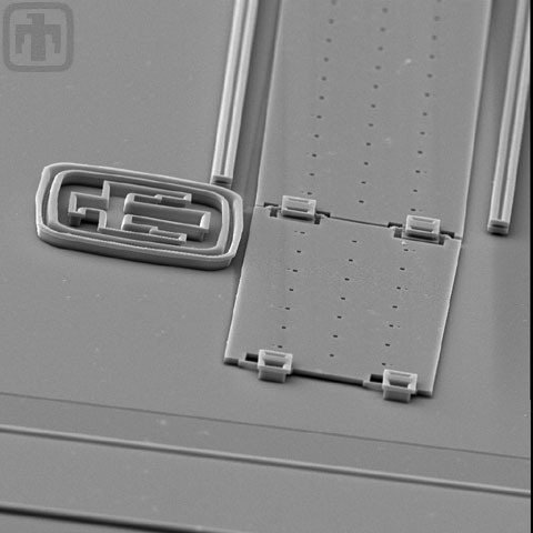
Alignment Clip
The structural layers supporting the clip indicate the precision achieved in fabricating MEMS.
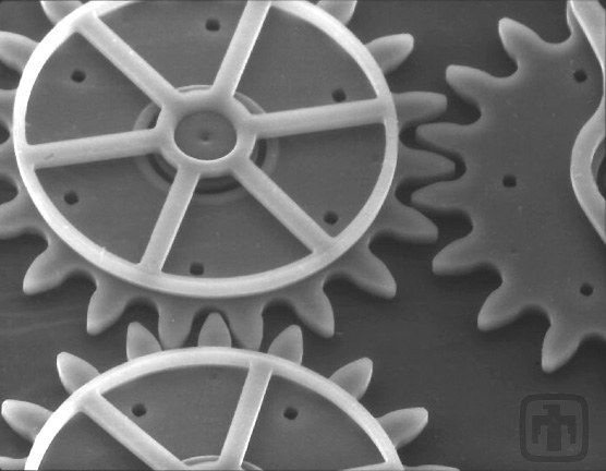
Dual Drive Gears
Two small gears rotate the large gear in the middle. This necessitates synchronizing four comb drives!
Engine Driving a Transmission
The microengine pinion gear (lower right hand corner) drives this 10:1 transmission.
Alignment Clip
This is another type of clip designed to keep gears in plane and meshed with each other.
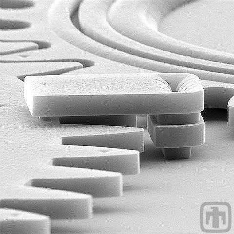
Wedge Clamp
This fancy looking clamp is actually a very simple device used to keep meshed gears co-planar.
Close-up of Transmission
The triangular holes that you see in this image were necessary because this transmission was fabricated before we invented planarized polysilicon.
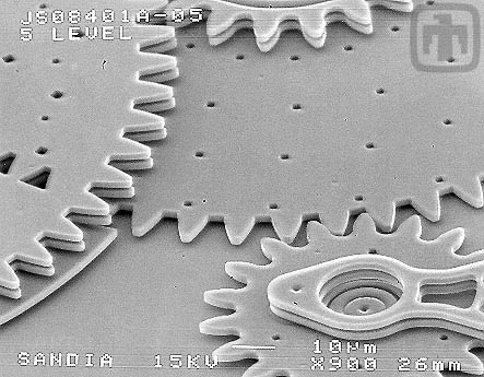
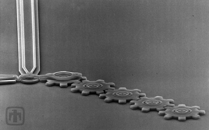
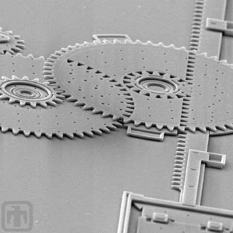
Six-gear Chain
All gears are driven sequentially by the drive gear (top center). The fixed guide plates (mounted to the tops of the gears' shafts) are clearly visible. Gear chains such as this one have been driven at speeds up to 250,000 RPM.
Close-up of Transmission
A microengine drives this 10:1 transmission.
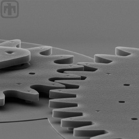
Six-gear Chain
View of six-gear chain, slightly from the side, showing the thickness of the gears.
Six-gear Chain Close-up
Close-up of the chain of meshed gears, and the guide plates.
Five-gear Chain
One of the first gear chains fabricated at Sandia, consisting of five gears in a linear arrangement.
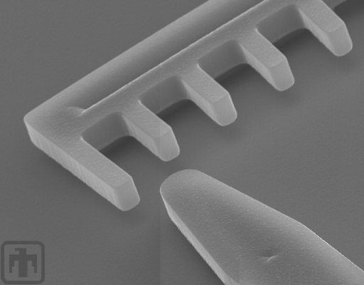
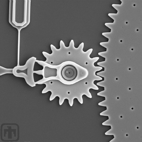
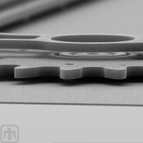
Indexing Motor - 2nd View
The indexing teeth on both sides of the gear are clearly visible. These teeth are key to the gear indexing forward one unit at a time.
Close-up of One of the Index Teeth
One of the indexing teeth is meshed with the gear at all times - this maintains the position of the index.
An Incredible Close-up of the Indexing Gear
In this view we can see the index gear is slightly inserted into the well.
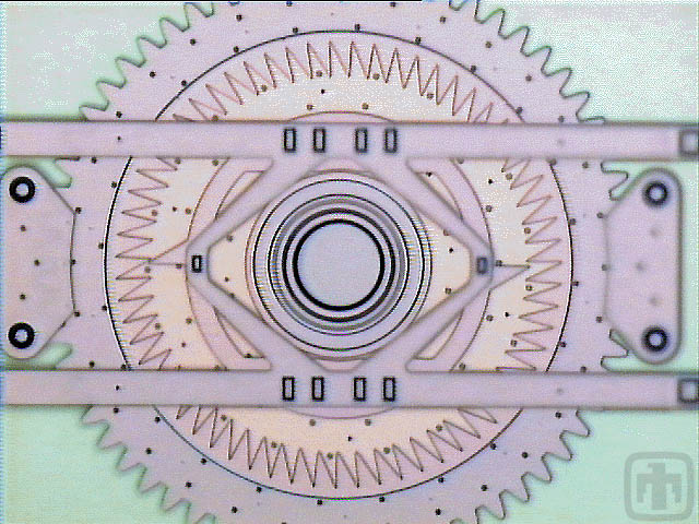
Indexing Motor - Color View
Indexing Motor - Color View
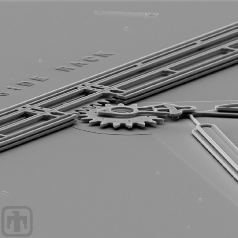
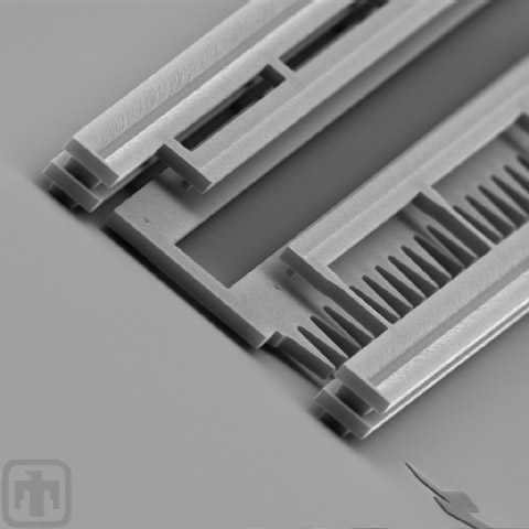
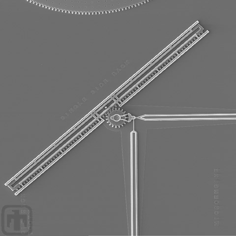
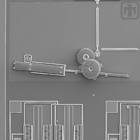
Linear Rack and Drive Mechanism
The comb drives (top and right) rotate the main drive gear, which is meshed with a linear rack. This mechanism converts rotational motion into linear motion to perform work.
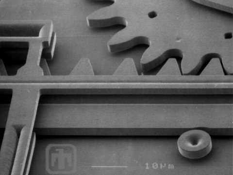
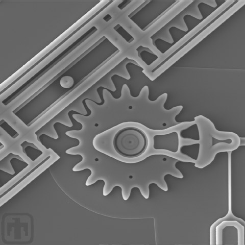
Linear Rack Close-up
Close-up of linear rack, rack guides, drive gear, and drive linkage.
Drive Gear Interaction
The meshed gear teeth of the drive gear and the linear rack.
Drive Gear
A close-up of the drive gear, linear rack and guide.
Rack Height
This view was captured at an angle to show the relative height of the device over the plane of the wafer.
Rack Structure
This close-up SEM allows us to see the 3D structure of the linear rack.
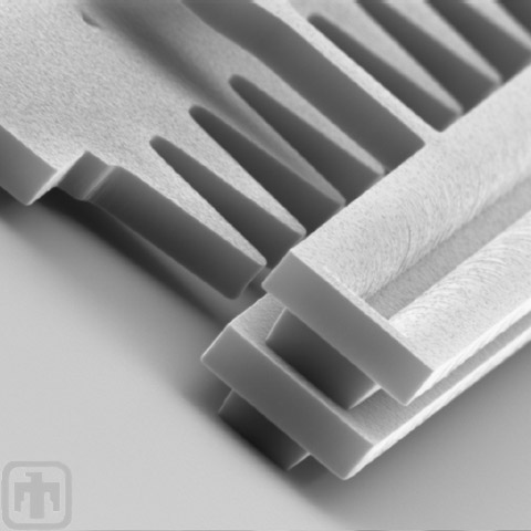
Teeth in Detail
Here is a close-up of the teeth on the linear rack.
Double-sided Rack
A two-sided rack that is propelled by a transmission and drives a mirror up, out of plane.
Single-sided Rack
The gear driving this single-sided linear rack is positioned at approximately a 45 degree angle to the rack.
Rack Close-up
A close-up view of the single-sided linear rack.
Rack Structure
This image, taken at an angle, shows the multi-layered structure of a linear rack.
Close-up of Drive Gear Hub
Close-up of Drive Gear Hub
Grain of Pollen and Red Blood Cells
Drive gear chain and linkages, with a grain of pollen (top right) and coagulated red blood cells (lower right, top left) to demonstrate scale
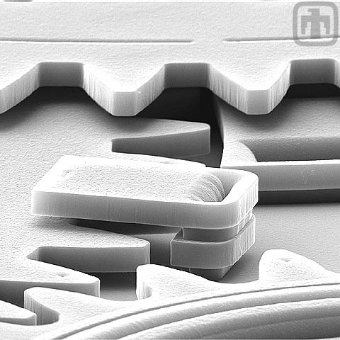
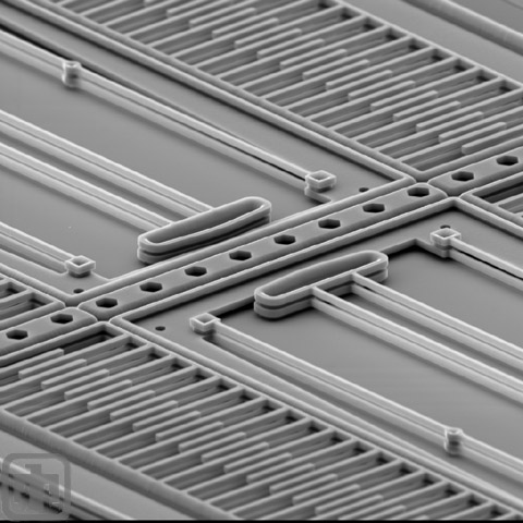
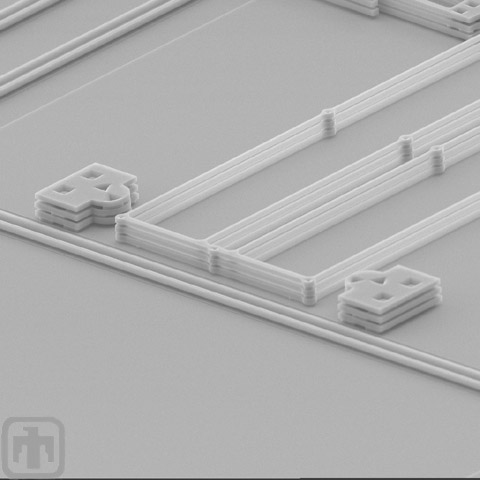
Two-layer Springs
Two-layer construction of springs provides greater out-of-plane stiffness, reducing stiction. At upper left, a travel stop limits lateral range of motion of spring.
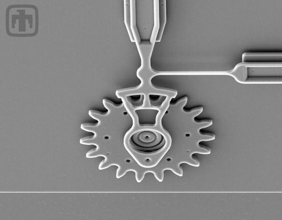
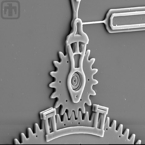
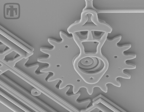
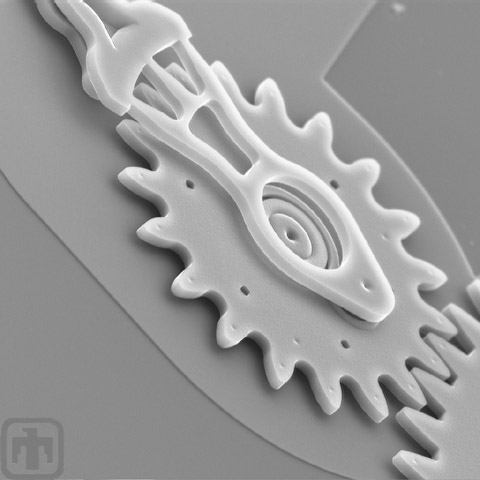
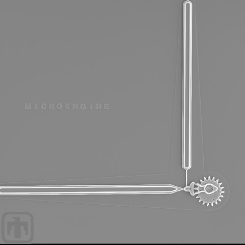
19-tooth Gear, and Linkage Arms of the Microengine
19-tooth Gear, and Linkage Arms of the Microengine
Meshed Gears
A microengine gear meshes with another gear.
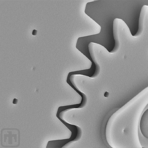
Gear Tooth Close-up
Close-up view of a gear tooth of a microengine.
Retaining Clips
A drive gear rotates the large gear. Clips keep the large gear in-plane.
Drive Gear Side View
Side view of a microengine drive gear meshed with another gear.
Drive Gears
This drive gear rotates a gear that is about ten times larger in
Drive Gear, Pin Joint, and Hub
A microengine drive gear, pin joint, and hub are all seen from the linkage arm side, illustrating just how they fit together.
Meshed Gears Close-up
A drive gear meshed with another gear, close-up view.
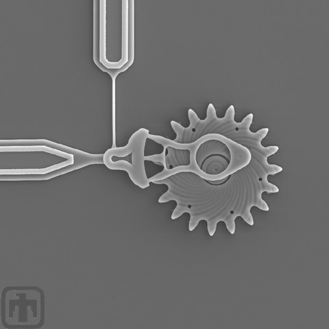
Microengine
This view of the microengine includes the drive arms, the pin joint and the drive gear.
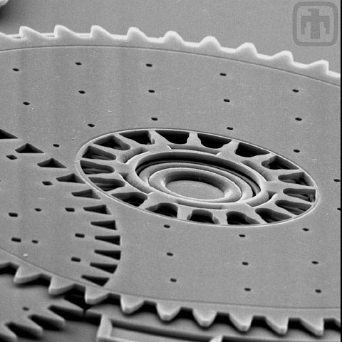
Air-Cushioned Gear
The spiral grooves in this drive gear channel air to the center of the gear; the air then provides a cushion.
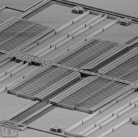
Comb Drives
Comb drives of a 3-layer polysilicon microengine are shown here. The springs in the center provide the restoring force, returning the electrostatic comb teeth to their original position.
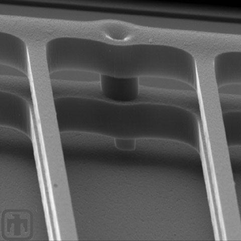
Travel Stop
This small component is a travel stop, used to limit the lateral displacement of the comb springs.
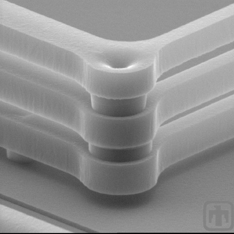
Comb Drive Springs
This view of the corner of comb drive springs shows that springs fabricated in the 5-layer surface micromachining process have an additional structural layer.
Comb Drive Springs
In this view of the comb springs, the interconnect is visible.
Comb Drive Springs Close-up
This is an extreme close-up of the comb drive springs. An interconnect between layers is included in this view.
Comb Drives and Springs
Although fabricated in the 5-layer process, the resulting structures are not far off the wafer substrate. Powerful magnification is necessary to see these comb drives and springs.
Travel Stops and Comb Springs
Travel stops and comb springs of a device fabricated in the 5-layer process are shown here.
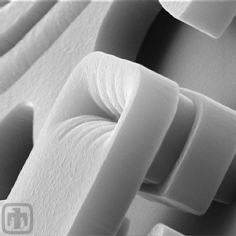
Pin Attachment Point
The pin connects to the drive gear of the microengine at just one point. The rest of the linkage hovers over the gear, allowing it to move freely.
Flex Joint
A flex joint is shown attached to a drive gear. Flex links develop little friction because they are devoid of moving parts.
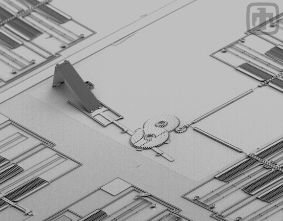
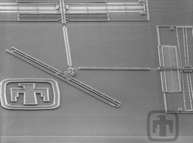
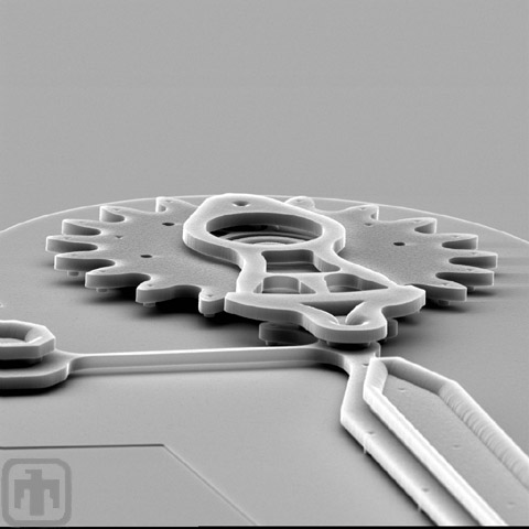
Silicon Mirror and Drive System
A mirror system design; in this system the mirror is elevated by a three-gear torque-multiplying system. The mirror is shown in the upright position.
Silicon Mirror Assembly Close-up
Close-up view of previous device; detail of rails and hinges is visible.
Polysilicon Mirror Assembly Close-up
A fixed-end view of the elevated mirror and the drive assembly.
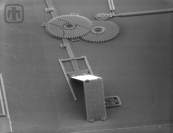
Hinged Polysilicon Mirror and Drive Motors
Polysilicon layers fabricated to "fold" on hinges as motors drive linear racks, thereby tilting the flat mirror structure out of plane.
Transmission, Rack, and Polysilicon Mirror
The transmission and linear rack elevate the mirror located in the lower-right of the frame.
Polysilicon Mirror Hinge Close-up
Polysilicon Mirror Hinge Close-up
Pop-up Polysilicon Mirror
Aerial view of a pop-up mirror.
Polysilicon Mirror Hinge
Please note the complex design of the hinge. This device is batch fabricated, with no assembly required
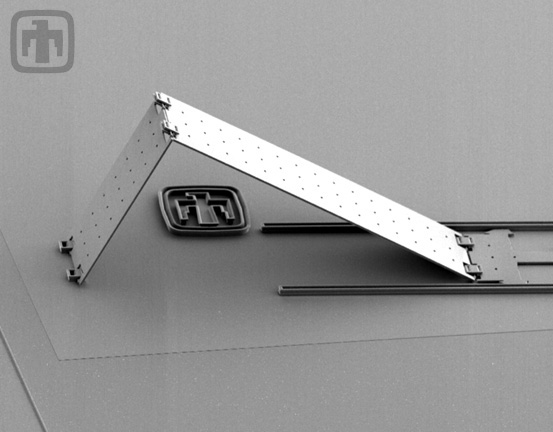
Pop-up Polysilicon Mirror
This image of a pop-up mirror, taken at an angle, includes the Sandia National Laboratories Thunderbird Logo and the hinges on the linear rack.
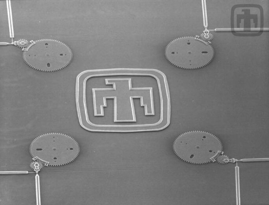
Optical Encoders
Four optical encoder wheels. Each wheel has four positions (00, 01, 10, 11) which can be switched mechanically. One of four signals from fixed-position lasers will be reflected, based on the position of the main encoder wheel..
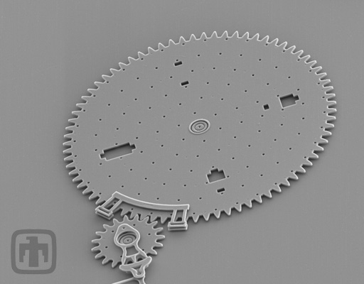
Optical Encoder
Close-up of an optical encoder gear.
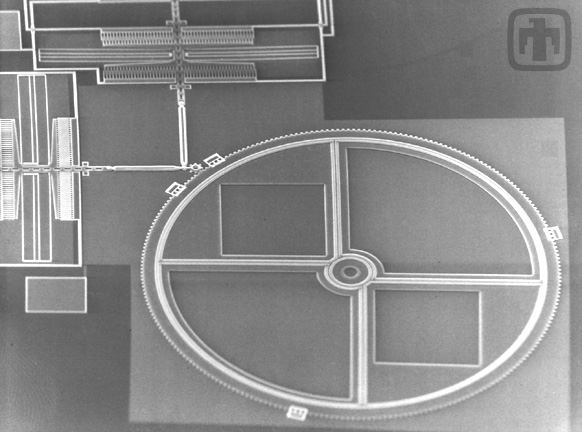
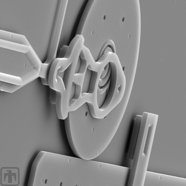
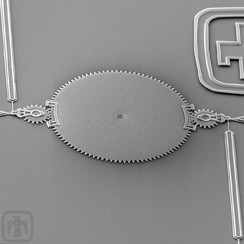
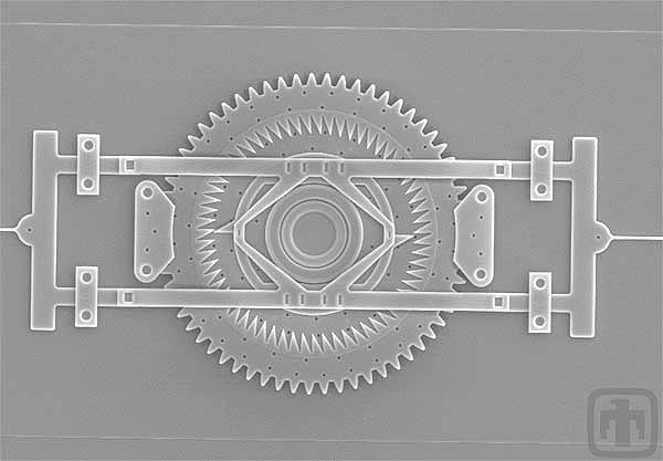
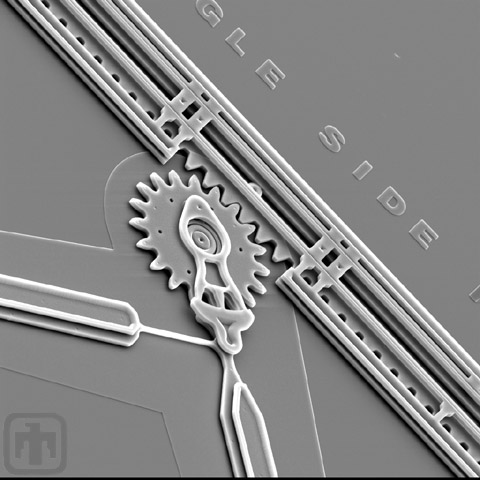
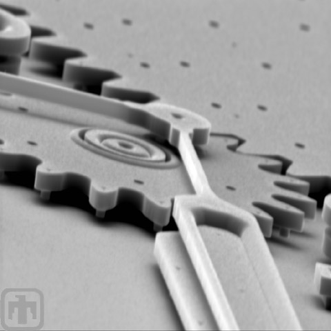
Optical Shutter Device
In this image are the comb drive motors, linkage mechanisms, and the large optical shutter. Because of the guide rails, the shutter can be rotated at very high speeds.
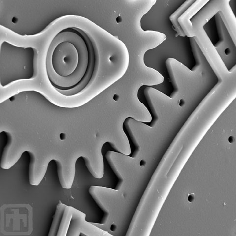
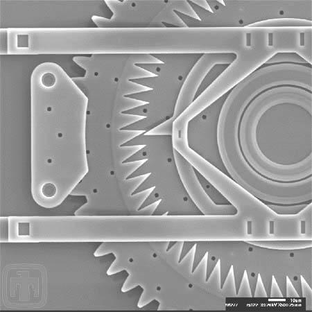
Close-up of Optical Shutter and Drive Gear
In this image it is possible to see the clamp attached to the substrate, and the pin joint and hub fit together.
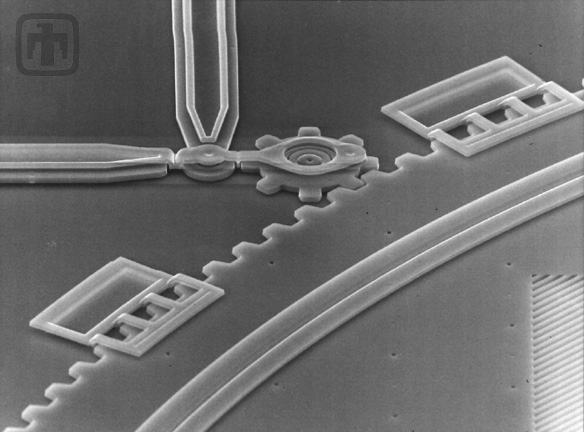
Optical Shutter and Drive Gear
Please note the intricate design of the hub of the drive gear.
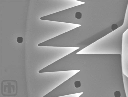
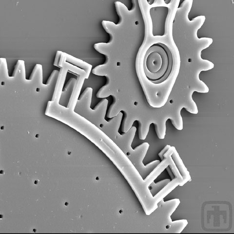
Close-up of Optical Shutter and Guide Tails
The guide rails are necessary to keep the optical shutter (large) gear from tilting out of plane when torque is applied by the drive (small) gear.
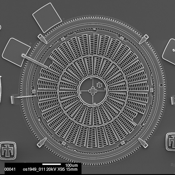
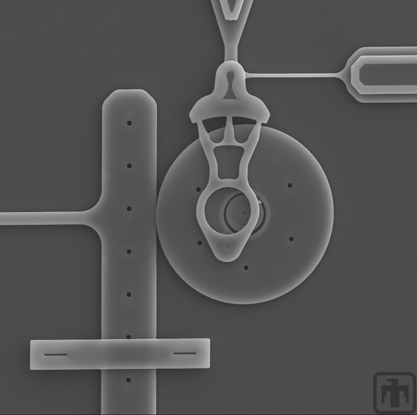
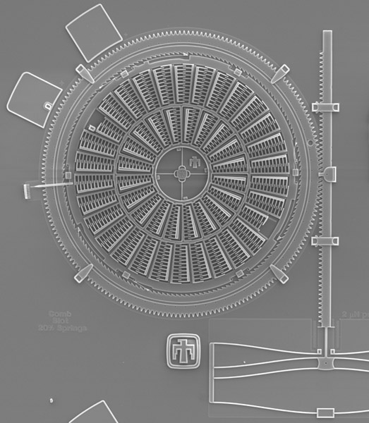
The Torsional Ratcheting Actuator (TRA)
The TRA uses a rotationally vibrating (oscillating) inner frame to ratchet its surrounding ring gear. Charging and discharging the inner interdigitated comb fingers causes this vibration.
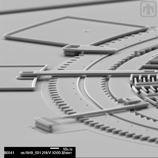
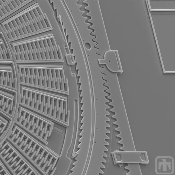
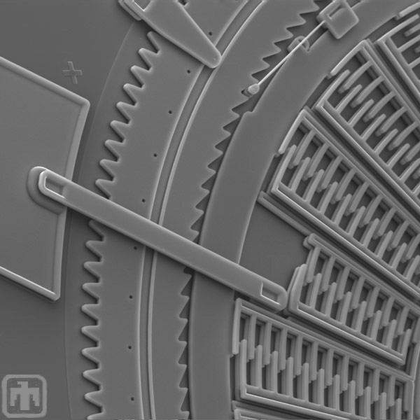
Angle View
Visible in this image: the outer ring gear along with (front to back):a pointer that indicates the degrees of oscillation of the inner frame, the electrical interconnect that supplies power to the engine, and a clip that holds the ring in place.
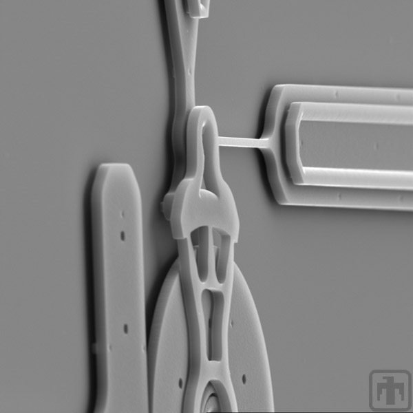
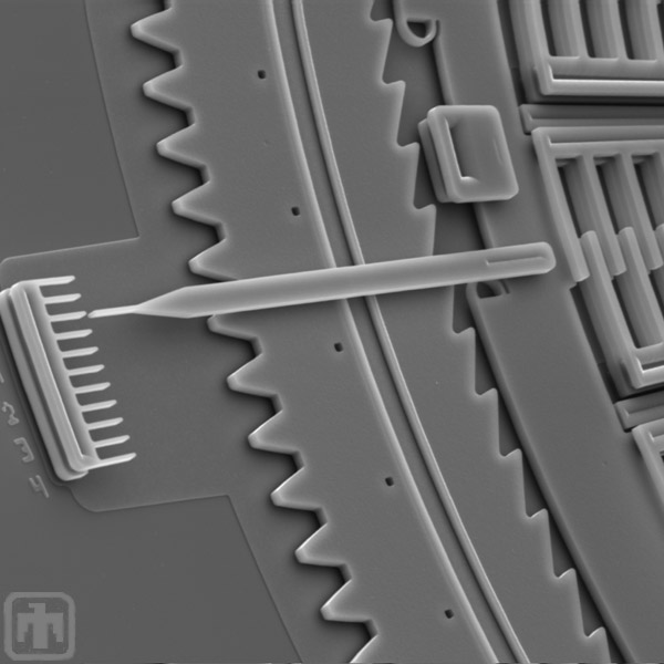
Force Testing Mechanism
A spring scale after it has been distorted by the force produced by the TRA.
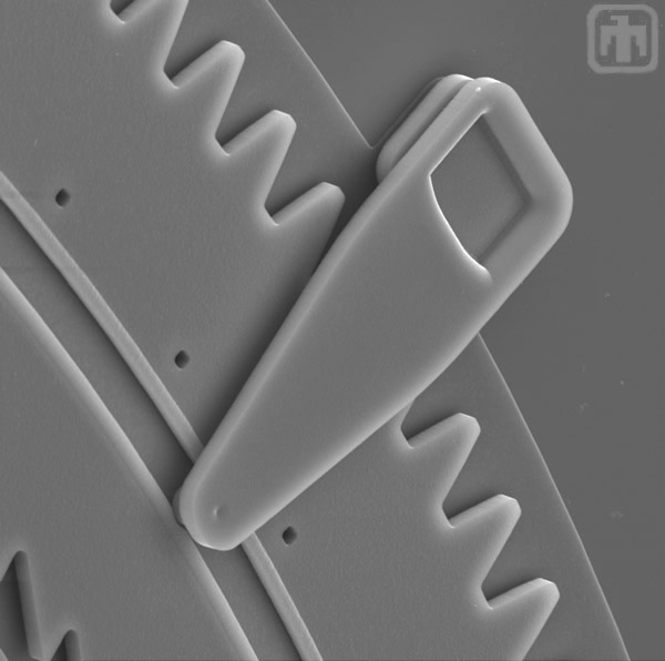
Ratchet Pawl
In this image, one of the TRA's ratchet pawls is visible. The pawls convert the small oscillations of the inside frame into a continuous rotation of the surrounding gear.
Force Testing Mechanism
This is a close-up view of the linear rack that delivers the TRA's force to the spring scale so that it can be measured.
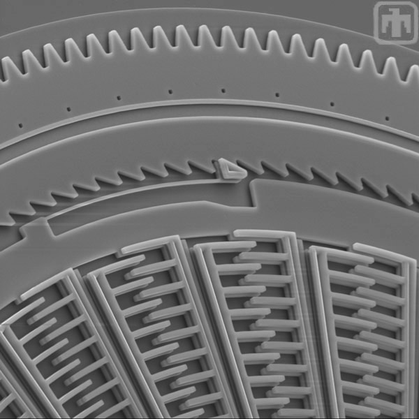
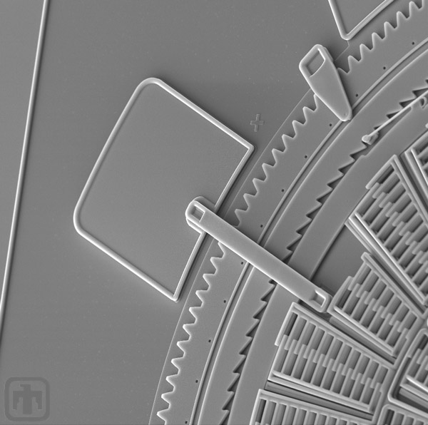
Gear Constraint
This is a close-up of one of the clips that hold the outer ring gear in plane.
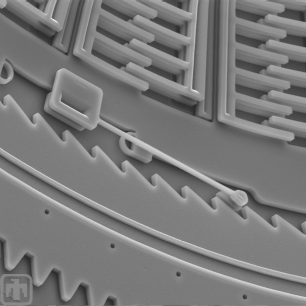
Electrical Interconnect
The arm, or beam, in the center of this image is an electrical interconnect that delivers electrical signals which power the TRA.
Angle Indicator
This pointer indicates the number of degrees of oscillation of the inner frame.
Electrical Interconnect
This is another view of the electric interconnect.
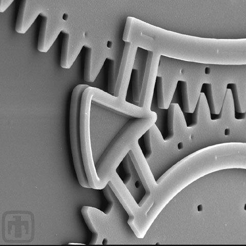
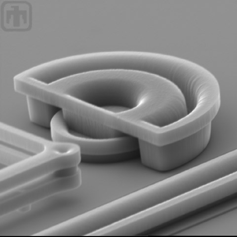
Anti-reverse Mechanism
This anti-reverse mechanism ensures that the ring gear can rotate in only one direction.