Computer modeling aids solder reliability in nuclear weapons
Solder isn’t the first thing that comes to mind as essential to a nuclear weapon. But since weapons contain hundreds of thousands of solder joints, each potentially a point of failure, Sandia has developed and refined computer models to predict their performance and reliability.
“Computational modeling of solder joint fatigue has become critical to Sandia and its role in the current nuclear weapons life extension programs, even before production assembly at the Kansas City National Security Campus,” says materials scientist Paul Vianco, who works with material modeler Mike Neilsen. “Sandia uses the computational model to solve manufacturing issues as well as assess the impact of design changes on solder joint reliability.
“This is critical as we finalize designs and head into production,” he says.
Anything with circuit boards requires countless solder joints, and miniaturization of electronics has vastly increased the number in printed wiring assemblies. Vianco lists two examples among a multitude of printed wiring assemblies for weapons: one with more than 900 solder joints, 400 on a single component; the other with about 300 joints.
Sandia has advanced computational modeling to the point it can help guide component design decisions and assembly processes at the Kansas City National Security Campus, establish qualification and acceptance test definitions and provide long-term reliability of solder interconnections in the stockpile, he says.
“In the early stages of model development, we could sit down with designers and give them a very broad reliability window for solder joints. It was a case of saying, ‘Well, you’re not going to get into a lot of trouble because we know what’s going to happen here and here,’’’ Paul says, stretching out his hands. “What was happening in here” — the space between his hands — “could not be predicted with any confidence that allowed the engineers to use the models to guide their designs of electronic assemblies.”
The making of a solder model
The current solder model resulted from years of research and collaborations with universities and others. Sandia has modeled solder performance for more than 30 years, increasing models’ fidelity based on improved knowledge of properties of materials and experiments to develop and then validate the models.
The key, however, is that today’s models provide quantitative as well as qualitative data.
Qualitative engineering judgments are based on experience and comparing outcomes — A is better than B. Quantitative predictions are explicitly based on the physical behavior of a material in a design rather than a comparison with another material, and can say, for example, A is a better design than B because it will last X number of years longer.
That saves enormous amounts of money by eliminating the need to fabricate samples and the time required for equipment operations and data analysis, Paul says. Modeling can provide answers in one to two weeks instead of the months needed for experiments, he says.

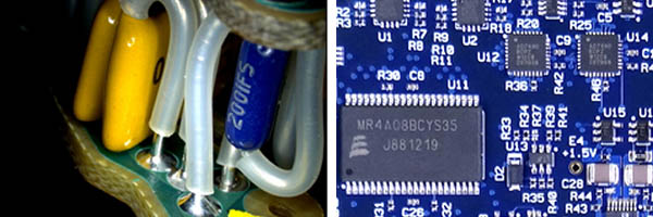
Traditional plated through-hole solder joint technology (left photo); Advanced surface mount solder joint technology (right photo)
Mike said his late mentor, Steve Burchett, pushed for Sandia’s early investment into computer models that could be used to predict when thermal mechanical fatigue cracks would start and grow in solder joints. He said Burchett recognized there was less margin for error as Sandia moved from plated through-hole interconnects to newer, more complex, surface mount assemblies.
Plated through-hole solder interconnects refer to drilling holes through printed circuit boards, plating the holes with copper, pushing component leads through the holes and soldering them in place. Surface mount components are soldered to pads on the top or bottom of printed circuit boards.
Experimental characterization work fed into models
Paul and colleagues started experimental characterization work in the 1990s that provided data for a unified creep plasticity model that captures both creep of solder at low stress levels and plastic deformation at higher stress levels, Mike says. The model accurately described the mechanical response of solder to slow loading typically generated during thermal cycling. Recent experimental material characterization by researcher Brad Boyce and colleagues helped refine the model to capture the mechanical response of solder under fast loading rates like those generated by shock and vibration, he says.
Sandia validates models by accelerated aging, thermal cycling tests to quantify the statistical reliability of solder joints. Paul’s team designs and builds printed wiring assembly mockups scaled to the size of real assemblies, then tests them in research ovens that cycle temperatures between set maximums and minimums to record any electrical failures in solder joints. The team analyzes the failure to confirm it was due to the expected solder fatigue and not some other, unexpected cause.
“Today, we’re performing the thermal cycling experiments, collecting the data, doing the statistical analysis on that data to determine the long-term reliability of area array solder joints,” Paul says.
Researchers validate solder fatigue crack initiation and growth predictions by comparing the model’s predictions with experimental results for different components: surface mount resistors and capacitors, leadless ceramic chip carriers, plastic ball grid arrays and the like. “Close collaboration between materials scientists and materials modelers is essential for the creation of good material models. We can accurately predict crack initiation locations, crack paths and the number of cycles needed to grow fatigue cracks,” Mike says.
The model also has generated some surprising results. “For example, voids in solder look bad but a uniform distribution of voids generally has little effect on fatigue life,” Mike says. He joked, “Maybe we should be using solder foam — if we could just figure out how to make it.”