Cubit
15.3 User
Documentation![]()
Cubit
15.3 User
Documentation![]()
In addition to specifying intervals explicitly based on a known count or size, CUBIT is able to compute interval sizes automatically based on characteristics of the model geometry. The following automatic interval size setting command can be used:
{geom_list} Size Auto [Factor <factor> ] [Individual] [Propagate]
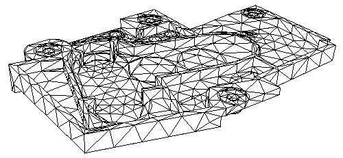
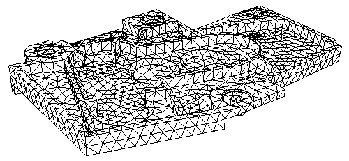
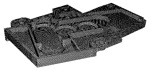
Vertices are not valid in the geom_list for this command. Automatic interval size assignment works by examining the geometric characteristics of the entities in the geom_list and assigning a heuristic size to the entities and their child entities. The factor may be a floating point number between 1.0 and 10.0, where 1.0 represents a fine interval size and 10.0 represents a coarse size. Figure 1 shows an example of different auto size specification on a CAD model.

(a) auto size factor = 7.0

(b) auto size factor = 5.0

(c) auto size factor = 1.0
The user may assign the interval size to be the arc length of the smallest curve contained in the specified entity or entities using the following command:
{geom_list} Size Smallest Curve
Vertices are not allowed in the geom_list for this command. This command assigns a soft interval firmness.
An automatic interval size with an auto size factor of 5 will automatically be computed and applied to any curve for which the following is true:
1) Intervals have not been explicitly defined by the user for a curve or its owning entities.
2) An Interval size has not been explicitly defined by the user for a curve and it is not possible to determine an interval size from its owning entities.
This automatic interval size is based upon all the geometry in the model. The automatic interval size specifications can be overridden easily by specifying another auto size factor or an explicit interval size.
If an auto size factor of 5 is undesirable for most meshing operations, the default factor may be changed by using the following command:
Set Auto Size Default <value>
where value is a number from 1 to 10. This will be the default auto size factor used when either a factor has not been specified on the size auto command or when an automatic interval size specification is used.
In previous versions of CUBIT a default interval of 1 was assigned to all entities. If this behavior is still desired, the following command may be used to enforce this condition:
Set Default Autosize [ON|off]
On many CAD models, arcs or small holes require that a finer mesh be specified around these entities in order to maintain reasonable mesh quality. To facilitate this, the user may specify the maximum angle an element edge may span on an arc. To change or list the maximum arc span, use the following commands
Set Maximum Arc_Span <angle>
List Maximum Arc_Span
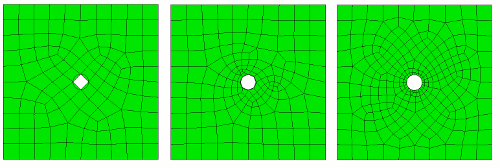
The angle parameter must be a positive value less than 360. The maximum arc span setting will only be used if there is not already a user defined interval set on the arc, and if the interval setting produces mesh edges which exceed the maximum spanning angle. Figure 2 shows the effect of three different maximum arc_span settings on a small hole using the pave scheme.

Figure 2. Maximum arc_span settings of 90, 45 and 15 degrees respectively.
Default arc span setting: In addition to setting an automatic size factor, if there are otherwise no user-defined interval sizes defined on an arc and no maximum arc_span has been set by the user when a tetrahedral mesh or triangle mesh is defined, a maximum spanning angle of 60 degrees will be used. Removing the use of the arc_span setting can be accomplished with the following:
Set Maximum Arc_Span Default
Note that once interval sizes have been defined when the entity has been meshed, it may be necessary to reset the interval settings (reset {geom_list}) to use a new maximum arc span setting when remeshing.