Geometry Tree
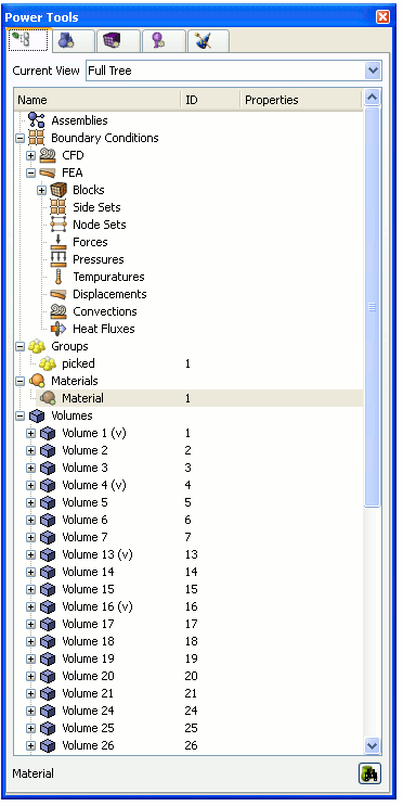
The geometry tree provides a complete graphical hierarchical representation of the parent child relationship of all geometric entities. The tree is populated as the model is constructed by Cubit. In addition to showing a hierarchy of geometric entities, the tree also shows Assembly Data, active Groups, and active Boundary Condition entities.
The tree works directly with the graphics window and picking. Selecting an entity in the tree will select the same entity in the graphics window. Selecting an entity in the graphics window will highlight the tree entry if that entry is currently visible. If an entity's visibility is turned off, the icon next to that entity in the geometry tree will disappear.
If the tree entry is not visible the user may press the Find button located at the bottom of the tree. The first occurrence of the selected entity will be shown on the tree.
Virtual entities have a small (v) after the name to indicate that they are virtual entities.

Figure 1. Geometry Tree Window
Drag and Drop
The Tree View window supports drag and drop of geometric entities into existing boundary condition sets. To create boundary conditions, see the Materials and Properties menu on the main control panel, or right-click on one of the boundary condition labels and select the "Create New" option from the context menu. Geometric entities or groups can be added to blocks, nodesets, or sidesets by dragging and dropping inside the tree view window. Assembly data may also be organized in the geometry tree window through drag and drop.
Picked Group
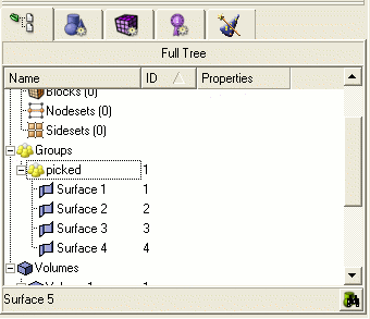
The current selections in the graphics window can be added to a "picked group" by selecting the "Add to Picked Group" from the Right click menu. Selections can also be added to the picked group by dragging and dropping onto the group from the geometry tree window. The picked group can be substituted into any commands that use groups. To remove an item from the picked group, use the "Remove from Group" option in the right click menu in the geometry tree or from the graphics window.

Figure 2. Picked Group
Right-Click Menu Functions
The geometry tree's context menu is sensitive to the type of item and the number of items selected. Functions that apply to the item type and number of selected items are available from the context menu. These include the following:
- Zoom To - Available for all geometric entities
- Rotate About - Change the center of rotation to the centroid of the entity without zooming
- Fly-In - Animated zoom feature
- Locate - Labels the selected entity in the graphics window
- Draw - Draw this entity by itself.
- Isolate - Similar to Draw command, but the display will not be refreshed with a graphics reset. To redisplay the model, select All Visible from the graphics window right-click menu.
- Transparency On/Off - Toggles transparency mode
- Visibility On/Off - Toggles visibility
- Rename - Allows you to rename entities from the tree. Clicking on a highlighted entity in the tree will do the same thing. This will also work for boundary condition entities (blocks, nodesets and sidesets)
- Mesh - Mesh selected entity at current settings.
- Delete Mesh - Available for meshed entities
- Reset Entity - Deletes mesh, and returns all settings to default values.
- Delete - Available when Volumes and Groups are selected.
- Create New Assembly/Sub-assembly/Part - You must specify the absolute path to create a new assembly, sub-assembly or part (e.g. /a1/p1). It may also be necessary to refresh the full tree before viewing changes.
- Add Selected to Part- Add the selected volume in the graphics window to the selected part on the geometry tree.
- Remove from Metadata - Deletes the selected part or assembly metadata information. An assembly must be empty to remove it
- View Metadata - List metadata in the command line workspace
- Rename Metadata - Allows you to rename a part or assembly
- Clean Metadata - Removes all parts and assemblies that are not associated with any geometric entities.
- List Volumes Without Parts - Lists all volumes that are not associated with a part in the output window
- Show Part Name/Description -Toggles the display of the part name/description in the tree.
- Goto Part - Finds the associated metadata part when a volume is selected.
- Measure - Available when two entities are selected or 1 curve is selected
- Refresh Full Tree - Used to return to main tree
- Collapse Tree - Available when entities are selected.
- View Descendants/Ancestors - Show this entity's individual hierarchy. Use the Refresh Full Tree option to return to main tree view.
- View Neighbors View adjacent entities. Use the Refresh Full Tree option to return to the main tree view.
- Create New Volume - Available when the user right-clicks over the Volumes (parent) label. Opens the geometry-volume-create panel
- Import Geometry - Available when the user right-clicks over the Volumes (parent) label. Opens import dialog.
- Create New Group - Available when the user right-clicks over the Groups (parent) label.
- Clean Out Group - Available when groups are selected. Removes all entities from group.
- Remove from Group - Available when groups are selected. Removes selected entity from the group.
- Add Selected to Block/Nodeset/Sideset - Add the selected entity in the graphics window to the chosen block, nodeset, or sideset in the geometry tree.
- Delete Selected from Block/Nodeset/Sideset - Delete the selected entity in the graphics window from the chosen block, nodeset, or sideset in the geometry tree.
- Create New Block/Sideset/Nodeset - Available when the user right-clicks over the respective Boundary Conditions (parent) label.
- Create New <boundary condition> - Available when highlighting desired boundary condition in the tree including CFD and FEA boundary conditions.
- Draw Block/Sideset/Nodeset - Draws the selected block/nodeset/sideset on top of existing entities
- Draw Sideset/Nodeset Only - Draws the selected nodeset/sideset independent of other entities
- Delete Selected Boundary Condition - Deletes any selected boundary conditions
- Draw Selected Boundary Condition - Draws selected boundary condition by itself
- Draw Selected Boundary Condition (Add) - Draws multiple boundary conditions
- List Selected Boundary Condition - Lists information about selected boundary conditions in the command line window
- Remove from Block/Sideset/Nodeset - Removes selected entity from the specified block, sideset or nodeset
- Cleanup (Tets) - Issues cleanup command for selected block. Only applicable for blocks composed of tet elements
- Remesh (Tets) - Issues remesh command for selected block. Only applicable for blocks composed of tet elements
- List Info - List information about selected entity in the output window.
![]()
![]()

